WELLOG
DEVIATION SURVEY
WELL DEVIATION:
During the course of
drilling a well, the direction of the drill may change. The causes vary,
however, the effect of changing formation hardness and drilling technique are
some of the major factors. Borehole deviation is defined as the angular change
from vertical.
In certain situations,
the direction of drilling is deliberately changed in order to intersect a
certain point below the surface. Directional drilling methods are used for this
application.
Borehole deviation is
measured in angular degrees from vertical often called inclination. When the
inclination is known, true vertical depth can be determined from the top of the
hole. True Vertical Depth (TVD) can be
determined from deviation information.
Exploration drill holes
may be drilled at a specified inclined angle to intersect a target such as a
mineralized ore body.
HOW IS DEVIATION MEASURED?
Early measurements of
deviation were performed using piezo-pendulum sensors and
potentiometer-pendulum sensors. Other deviation tools use a one-shot
photographic method or locking compass mechanism.
More recent electrolytic
technology uses a small fluid filled container with a geometric configuration
of fluid level sensors.
Ask about the WELLOG
basic x-y tilt sensor tool with RS-422. WELLOG provides the interface!
Improved techniques using
new technology include the following methods:
ACCELEROMETERS:
Recent advances in
semiconductors use surface micro-machined Poly-silicon springs also known as MEMS technology. These devices have given rise to a
family of low cost solid-state 2 and 3 axis accelerometers. Accelerometers
can measure gravitational acceleration forces from tens and hundreds of g’s down to fractional g forces. When used in
fractional g applications, accelerometers can measure angular displacement or
tilt from the vertical. WELLOG has recently developed MEMS based accelerometer
sensor systems that can detect fractional changes in borehole angle with
increments of .1 degree or less. Measurement of G force is non-linear. Our
sensor systems “linearize” the sensor output into a linear x-y axis measurement
of degrees. Single chip integrated circuit 3-axis accelerometers are embedded
in WELLOG deviation tools.
MAGNETOMETERS:
Recently, 3 axis
solid-state integrated circuit magnetic field sensors called magnetometers have come into the market.
They provide accurate, high resolution electronic compass and x-y axis tilt information. A magnetometer
can be incorporated into a digital electronic compass for azimuth information.
Azimuth information is logged with repeatable accuracy of less than one degree.
Magnetic azimuth and magnetic x-y tilt information may be used for borehole
directional surveys.
Ask about the WELLOG Mini-Mag heading sensor.
Tilt compensated compass
for open-hole boreholes:
Ask about the WELLOG ez-Mag vertically
oriented tilt compensated 360 heading and 90 degree x-y tilt sensor with
RS-422, RS-485 or RS-232.
Ask about the WELLOG Tractor-Mag Tilt compensated 360 degree heading and 90
degree x-y tilt with RS-422, RS-465, RS-232 or USB.
View an example of the
default NEMA format data produced by this system here.
As always WELLOG provides
the interface!
GYROSCOPES:
Solid-state gyroscopes
use a technology referred to as iMEMS. Three axis
solid-state gyroscopes can provide direction in steel cased holes and in
regions that are affected by magnetic mineralization. Rate sensing integrated
circuits offer capabilities in applications where magnetometers are unreliable.
COMBINATION SENSORS:
Combinations of sensors
measure tilt by measuring gravitational acceleration using a
x-y accelerometer and measure direction of tilt with reference to magnetic
north using a magnetometer. Magnetometers are reliable in most cases.
Magnetometers can become unreliable around machinery or when they are inside
steel well casing. When used in COMBINATION with rate gyros and accelerometers,
all three sensors provide input to a high speed processor that maintains
continuous orientation.
Applications within steel
casing or areas having anomalous magnetic fields: (NO PROBLEM!)
Rate Gyros offer a
solution to the problems associated with magnetometers. A combination x-y tilt
sensor using an accelerometer and a rate sensing gyro provides a robust
deviation measurement platform.
WELLOG NAVIGATOR: (NEW FOR 2011)
In the best case, a
combination of both a 3-axis rate gyroscope and 3-axis accelerometer sensor package
provides a complete sensor package. This combination results in measurement of
NINE degrees of freedom (DOF). The most advanced product in our line of
deviation instruments is a “WELLOG Navigator”. This borehole surveying package
can be combined with our V30 logger surface
well logging system and USB interface to a notebook PC.
Ask about the WELLOG
Navigator with RS-485 wire line driver and USB input to PC. It creates a
standard text file ready for immediate viewing.
Nine Degrees of Freedom:
Recent improvements in
navigation boards have resulted in a system referred to as an INERTIAL
MEASUREMENT UNIT (IMU). The IMU integrates a 3-axis Gyro, 3-Axis Magnetometer,
and 3-Axis Accelerometer.
WELLOG is developing a
wide range of IMU boards in airborne, surface, marine, and down-hole
applications.
CALIBRATION:
Deviation tools are
placed on a stand that is calibrated in degrees. As the tool is tilted from vertical,
thru each angular position, the response is noted. Because all logging tools
may change performance during logging, it is important to perform a field
calibration test before and after every logging job.
COORDINATE SYSTEMS:
The result of a sequence
of measurements of x-y tilt and directional heading information is combined
into a polar or rectangular plot for presentation. A rectangular presentation
affords a 3 dimensional view of the well or borehole in 3 dimensional space.
A polar plot is a
presentation of the direction of the well or borehole from the view of an
observer looking down hole from the location of the well at the surface. This
presentation resembles a target centered at the location of the well at the
surface and having concentric rings representing the displacement and direction
(in degrees) of displacement of the hole at given depths.
INTERPRETATION:
No one computational
method is always the “right” method, and the right
method to be used can be chosen from several methods.
Inclination (j) is taken to be the
angle of the well course from the vertical. Azimuth (q) is taken clockwise from
geographic north. In order to maintain a right handed coordinate system,
coordinate x increases to the north and y increases to the east.
The relations between
measured angles and rectangular coordinates are:
dx = sin j cos q dl = a dl
dy = sin j sin
q dl = b dl
dz = cos j dl = g dl
Where:
inclination = j Azimuth = q
The direction cosines a, b and g = defined in the above
equations represent the cosines of the angles between the well course and the
x, y, and z directions. The simplest method of computing a well course called
the tangential method, is to fit a series of
straight-line segments to the well course and establish the direction of each
segment by the lower of each pair of stations. The method is an extension of
the above equations applied to data from two sequential stations labeled a, b
so that
Dx = sin jb cos qb Dl = ab Dl
Dy = sin jb sin qb Dl = bb Dl
Dz = cos jb
Dl
= gb Dl
where the incremental distances are the differences
between values taken at a and b, for example, Dx = xb – xa. It is generally held that it is less accurate than
other methods and its use is not recommended (Wilson, 1968).
In more satisfactory
methods, some means of averaging the measurements taken at two adjacent
stations is utilized. The tangential method can be improved by averaging the
directional cosines of stations a and b. The result is
referred to as the balanced tangential method
Dx = ½ (aa+ ab) Dl
Dy = ½ (ba+ bb) Dl
Dz = ½ (ga+ gb) Dl
From: “Well Logging For
Physical Properties”, Joseph R. Hearst, Philip H. Nelson, McGraw-Hill, inc.,
1985
MODES OF MEASUREMENT:
Deviation can be measured
in several modes. The three modes are single shot, multi shot and continuous.
The more measurements, the more accurate the final analysis of the directional
survey will be.
HUMAN FACTORS IN LOGGING:
WELLOG is constantly
improving the process of logging wells. The logging process can be tedious, and
susceptible to human error. Often, well logging is performed after long periods
without rest or under conditions that make measurement difficult. Reducing the
complexity of setting up and operating logging systems can be part of the
design process.
KEEPING IT SIMPLE: Here’s an illustration of the calculations in
MS Excel : borehole navigation.xls
and a 3D view.
GREAT
THINGS IN THE MAKING!
WELLOG has made great
progress in making well logging easier and more reliable. New developments in
memory logging tools are examples. Making tools that are self contained and
wireless is an example.
NEW DEVELOPMENT:
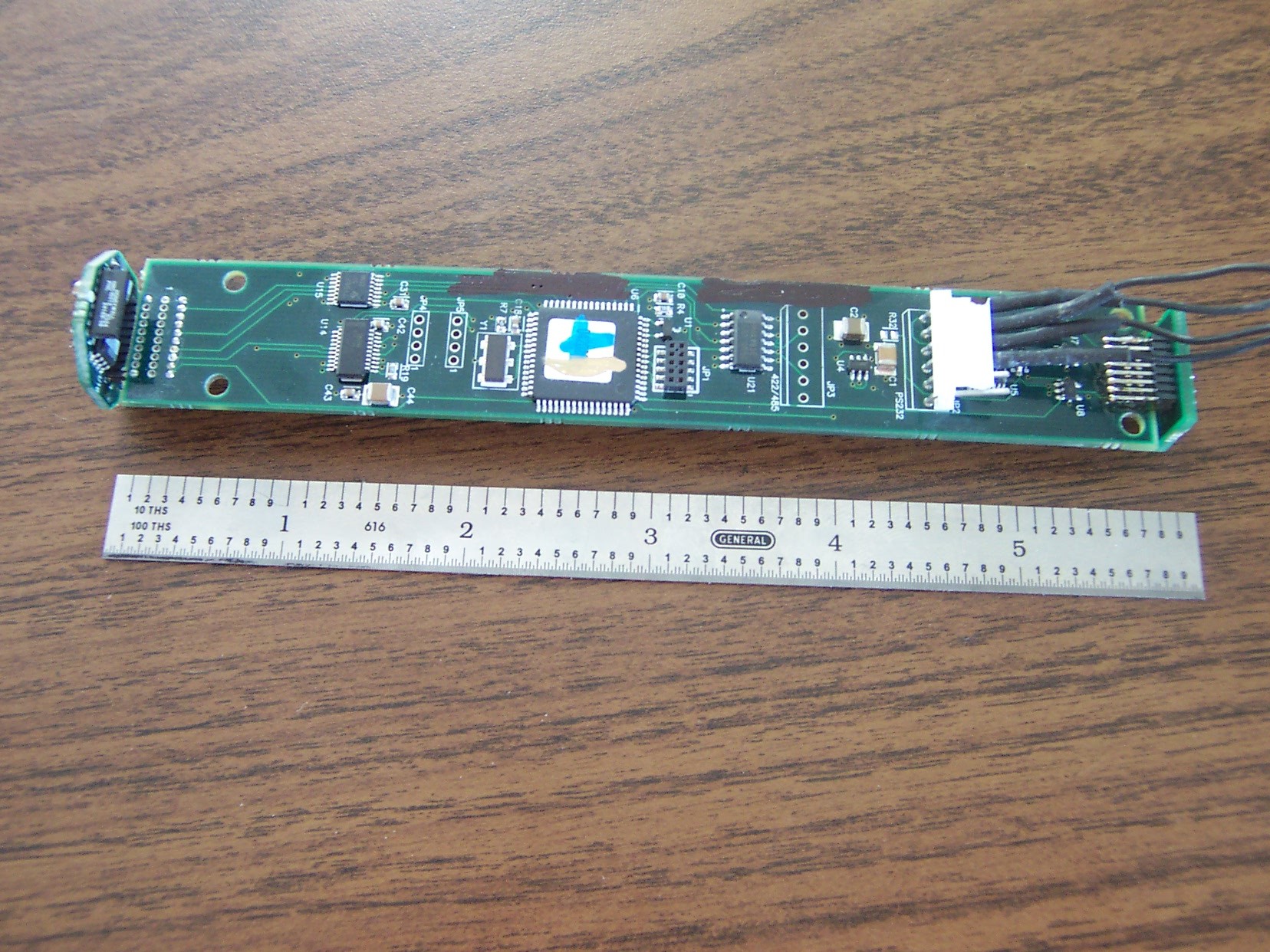
NEW! World’s smallest radio-modem memory deviation logging tool!
WELLOG has developed what
could possibly be the first of its kind commercially available microprocessor
based deviation logging tool.
This tool measures course
and tilt to less than one degree using solid-state accelerometers. The tool is
battery powered and rechargeable.
It is a memory logging
tool containing a radio-data modem for downloading memorized logging data.
OTHER APPLICATIONS
include slope stability alarms in mining. Avalanche
detection. Unmanned Aerial Vehicles.
This tool employs a
single navigation platform with NMEA data output. It’s available in a 1 ½ inch
“slim hole” tool housing memory mode or GO style 4
conductor tool head for wire line.
Simple.
Reliable.
Easy to use.
LOW COST:
WELLOG has developed
deviation tools using the most advanced solid-state devices available. In the
process, the design time has been short, the cost of
the components has dropped considerably because of competition in the world
market. Getting the latest technology can save you money! Ask WELLOG about the
competitive cost savings available on these tools.
Revised 11-07-2018 © 2004 - 2018 WELLOG All Rights Reserved